Convex Hulls
An algorithm to find the perimeter of a data set, and includes convex polygon overlap detection
Overview of Algorithm
 The idea is simple: find the minimum number of data points which represent the perimeter convex polygon
about a data set. There are many variations of this algorithm and the applications can
be critical; for example, an introductory machine learning problem is to construct
a boundary (a straight line with 2 weights in the simplest case) between two linearly
separable data sets, where linearly separable means that there exists some line that
perfectly differentiates the two data sets (all the data from one set fall on one side of
the line while all the data from the other set fall on the other side).
However, how does one know if the two data sets are linearly separable?
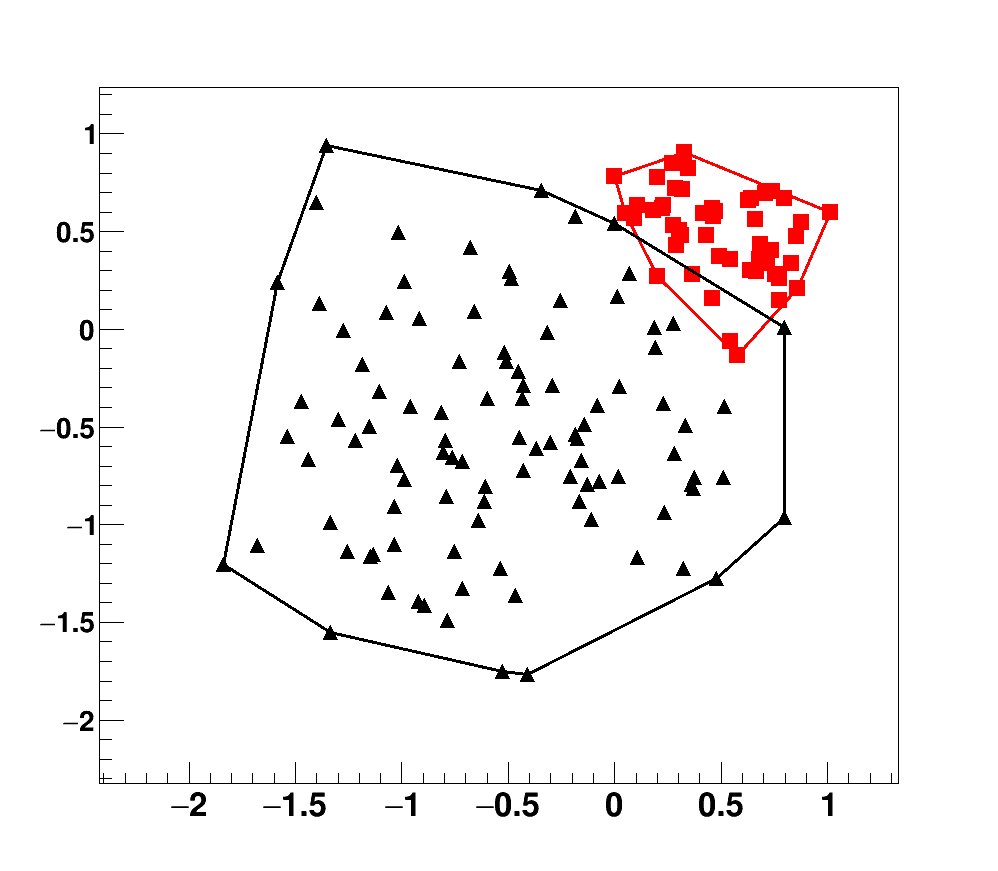
One method is to apply the convex hull algorithm to both data sets individually in order
to construct two polygons, then the polygons may be tested for overlaps in order to confirm (or not)
linear separability. Here are the major components of my convex hull algorithm,
which at the core consists of calculating smallest angles between carefully chosen vectors
(See Fig. 1 for an example in which the data are labeled):
The idea is simple: find the minimum number of data points which represent the perimeter convex polygon
about a data set. There are many variations of this algorithm and the applications can
be critical; for example, an introductory machine learning problem is to construct
a boundary (a straight line with 2 weights in the simplest case) between two linearly
separable data sets, where linearly separable means that there exists some line that
perfectly differentiates the two data sets (all the data from one set fall on one side of
the line while all the data from the other set fall on the other side).
However, how does one know if the two data sets are linearly separable?
One method is to apply the convex hull algorithm to both data sets individually in order
to construct two polygons, then the polygons may be tested for overlaps in order to confirm (or not)
linear separability. Here are the major components of my convex hull algorithm,
which at the core consists of calculating smallest angles between carefully chosen vectors
(See Fig. 1 for an example in which the data are labeled):
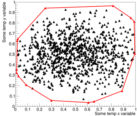
- Generate a data set. I generated points based on a Gaussian distribution with a mean and sigma of 0.5 and 0.25, respectively, as I did not want to points to wander too far.
- Each point needs to be indexed using some book-keeping integer for tracking purposes.
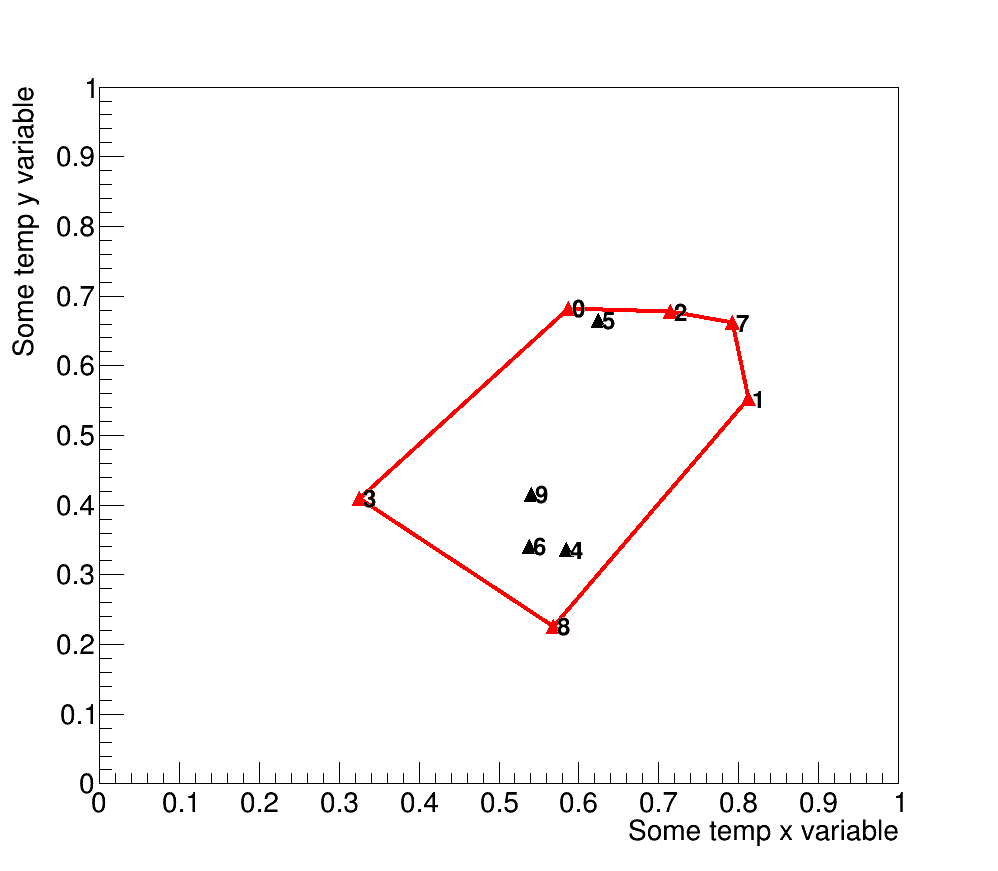
- Find the algorithm's starting point - I chose the point with the minimum y value, and if there are duplicates then I choose the point with the lowest x and y values, or the bottom-left point; this point by definition is part of the hull. The starting point in Fig. 1 is labeled as 8.
- Make a hull container which will be used to keep track of the points making up the perimeter polygon (or the hull), and insert the starting point as by definition this point must be apart of the hull. Also, it is useful to make a storage container that contains all the data points, which allows for element removal as we traverse the hull; this is the container that is used to find points to add to the hull.
- Construct a vector using information from the hull container; the first iteration consists of the first hull point 8 and the origin. The direction is important as we want to calculate minimum angles.
- Find the minimum angle between a test-case and the hull vector (origin and point 8); the test-point with the minimum angle is the next hull point, which is labeled by 1 and may now be removed from storage.
- Repeat. The next hull vector is built by points 8 and 1, then the minimum angle between this vector and a test-vector is the next hull point; in this case, it is given by point 7. Note that this strategy allows angles to be calculated by a simple dot product.
- Continue until we reach the starting point, hence the utility of the book-keeping device
Overlapping Convex Polygons
What if we are interested in the overlapping region between two convex hulls? Assuming that the hulls overlap, then the boolean AND operation results in another convex polygon. Determining the overlap can be difficult, but here is what I chose to do:
- Break the convex polygon P1 of N vertices into sub-triangles - I wrote a routine that takes the hull coordinates (arrays/vectors of x,y points) and returns N-2 triangles (in the form of arrays of x,y points).
- Loop through the other hull polygon, denoted by P2 which has M vertices,
and check to see if any of the x,y points live in the sub-triangles of P1.
The following function was used for this purpose:
where point p is the point to test in order to determine if it lives in a triangle of x and y coordinates denoted by p0, p1, and p2; if so, then the function returns true, otherwise false.bool in_triangle(point p, double* x, double* y){ point p0(x[0],y[0],-1); // triangle vertex point p1(x[1],y[1],-1); // triangle vertex point p2(x[2],y[2],-1); // triangle vertex double A = 0.5 * (-p1.Y() * p2.X() + p0.Y() * (-p1.X() + p2.X()) + p0.X() * (p1.Y() - p2.Y()) + p1.X() * p2.Y()); double sign = A < 0 ? -1 : 1; double s = (p0.Y() * p2.X() - p0.X() * p2.Y() + (p2.Y() - p0.Y()) * p.X() + (p0.X() - p2.X()) * p.Y()) * sign; double t = (p0.X() * p1.Y() - p0.Y() * p1.X() + (p0.Y() - p1.Y()) * p.X() + (p1.X() - p0.X()) * p.Y()) * sign; return s > 0 && t > 0 && (s + t) < 2 * A * sign; } - The inverse needs to be checked, i.e. check to see if any points of polygon P1 live in P2.
- Intersection points between P1 and P2 also need to be tracked if one desires the overlapping polygon; this can be achieved by simple vector intersection.
- All these points need to be tracked and put into an array in CW or CCW order in order to build a convex polygon.
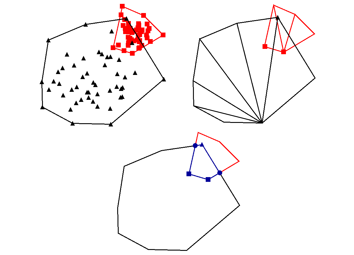
The result of the above logic may be seen by Fig. 3. Note that I am only concerned about the hull polygons, not the data within the hull (which only matter during the construction of the hull). The top-left panel displays the two hulls, denoted by Hred and Hblk. The top-right panel displays the result of the sub-triangularization method, and explicitly shows which hull vertices were detected using the above code snippet. In other words, the red squares are detected in Hblk while the black triangle is a point of the hull Hblk that has been detected in Hred. The bottom panel displays the overlapping result in blue, which is another convex polygon. The markers are coded by shape where the meaning of the square and triangle markers has just been discussed; the circle markers, however, represent intersection points between the two convex hulls and must be considered when constructed the overlapping hull. Note that in the context of linear separability, none of this is necessary; one only needs to check to see if a point of hull Hblk exists within Hred and vice versa.